
Insights · Passive Sensing & Detection
Illuminators of Opportunity: Passive Radar's Geometry, Gifts, and Blind Spots
A radar does not need its own transmitter. The world is already flooded with radio energy — FM broadcasts, digital television, cellular downlinks — and a receiver that compares those signals against their faint reflections from aircraft can detect and track targets while emitting nothing at all. This is passive bistatic radar. Its physics offers a defender remarkable gifts, and its geometry imposes equally definite blind spots. Both are worth understanding precisely, and both are thoroughly documented in the open literature.
Radar with a borrowed flashlight
A conventional radar is monostatic: transmitter and receiver share one location, and the radar shouts and listens for its own echo. A bistatic radar separates the two — and a passive bistatic radar goes further, not transmitting at all but borrowing an "illuminator of opportunity": a broadcast tower that was going to transmit anyway [1][2]. The defender's gains are immediate. A silent sensor cannot be located by the enemy's electronic reconnaissance, cannot be homed on by anti-radiation weapons, and needs no spectrum license. The costs are equally structural: the defender controls neither the waveform nor the transmitter's location, and must live with whatever geometry and signal the broadcaster provides. Everything interesting about passive radar follows from that bargain.
The geometry: ellipses, and why sensitivity is not a circle
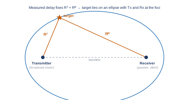
A monostatic radar measures the round-trip time to a target, which places the target on a circle around the radar. A bistatic system measures the total path transmitter → target → receiver, which places the target on an ellipse with the transmitter and receiver at its two foci — the same shape you draw by looping a string around two pins and pulling it taut with a pencil. Each measured delay corresponds to one such ellipse, so a single transmitter–receiver pair localizes a target to an elliptical contour, not a point.
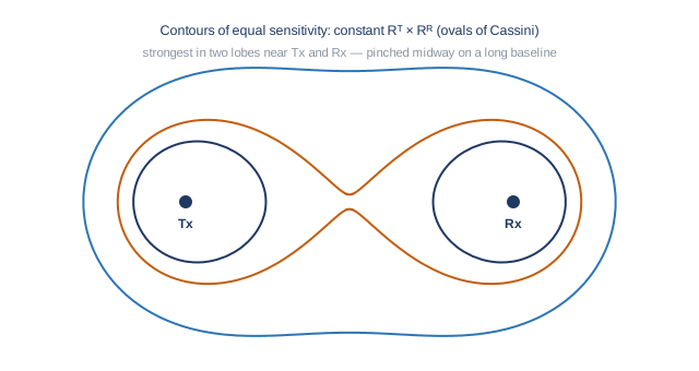
Sensitivity has its own, different geometry. The received echo power falls off as the product of the two path distances squared — proportional to 1/(RT²·RR²), where RT and RR are the transmitter-to-target and target-to-receiver ranges. Contours of constant sensitivity are therefore curves of constant product of distances, known as the ovals of Cassini [2]. Their practical meaning is easy to state: detection is strongest in two lobes, one hugging the transmitter and one hugging the receiver, and weakest midway between them when the two are far apart. A passive radar's coverage map is not a neat disc; it is a shape dictated by where the broadcast towers happen to stand — which is why site selection and multi-illuminator planning dominate real deployments.
What the borrowed signal gives you — and what it withholds
Range resolution — how finely a radar can separate targets in distance — is set by signal bandwidth: the resolution is c/2B, the speed of light divided by twice the bandwidth. Bandwidth is the fineness of the ruler. An FM radio station occupies only about 100 kHz, giving a range resolution on the order of 1.5 kilometers: FM-based passive radar sees that something is there and how fast it moves, coarsely in range. Digital television is a far better ruler — roughly 8 MHz of bandwidth yields resolution around twenty meters — at the price of operating at higher frequency with different propagation. The literature even documents that FM performance varies with program content: speech, with its pauses and narrow spectrum, makes a poorer radar waveform than dense music, a genuinely charming result that follows directly from the mathematics of correlation [1][3].
Two further physical gifts deserve plain statement. First, wavelength: FM broadcasts near 100 MHz have wavelengths around three meters — comparable to the dimensions of small aircraft. Targets whose size is of the same order as the wavelength scatter in the resonance region, where reflection depends on gross size rather than fine shaping; the shaping and coating techniques that reduce radar cross-section at microwave frequencies purchase much less at meter wavelengths [2]. Second, time: because the broadcast is continuous, a passive receiver can integrate for seconds rather than the microsecond dwells of a scanning radar. Doppler resolution improves with integration time, so passive systems achieve exceptionally fine velocity discrimination — which is precisely the tool needed to separate a slow, small aircraft from the surrounding sea of stationary clutter.
The first hard problem: hearing a whisper beside the loudspeaker
The receiver's fundamental difficulty is that the direct signal from the transmitter arrives vastly stronger than any target echo — by factors the literature routinely quotes at eighty to a hundred decibels, a ratio of ten billion or more [1][3]. The situation is exactly that of standing beside a concert loudspeaker while trying to hear the music's echo from a distant wall. The discipline's answer is a layered cancellation architecture: a reference antenna captures the clean direct signal, adaptive filters subtract it (and its multipath copies) from the surveillance channel, and antenna design places spatial nulls toward the transmitter. How completely this suppression is achieved effectively sets the system's detection floor, and it is the engineering heart of every practical passive radar.
The second hard problem: the geometry's built-in blind spots
Three blind spots follow from the mathematics itself, not from any implementation's weakness. A target crossing the direct baseline between transmitter and receiver enters the forward-scatter region: its apparent reflectivity surges dramatically — a well-documented enhancement — but range information collapses, since every point on the baseline yields the same total path length. A target flying tangentially, along a constant-total-path ellipse, presents near-zero bistatic Doppler and sinks into the same spectral region as stationary clutter, the "zero-Doppler ridge" where detection is hardest. And the entire system inherits the illuminator's fortunes: terrain masking between tower and target, transmitter maintenance, or — soberingly relevant in wartime, and visible in public reporting — broadcast infrastructure being damaged or deliberately shut down. The standard remedy for all three is the same: diversity. Multiple illuminators of different types and positions, feeding multiple receivers, ensure that a target sitting in one pair's blind spot is squarely in another's sensitive lobe.
From one ellipse to a track: the network view
A single transmitter–receiver pair yields an ellipse, a Doppler history, and perhaps a coarse bearing. Localization comes from intersection: two or more pairs observing the same target cross their ellipses at its position, and a network of receivers exploiting several broadcast sources becomes a distributed localization system whose accuracy grows with geometric diversity. At that point the passive-radar problem hands off to the distributed-fusion problem — associating detections across pairs, fusing them over constrained links — treated elsewhere in this series. The two literatures compose naturally, because they were always two halves of the same architecture.
The honest summary
Passive radar offers detection that cannot be jammed at the source the defender doesn't own, cannot be targeted at the receiver that never transmits, operates in a wavelength regime unkind to stealth shaping, and discriminates slow movers by Doppler with a patience active radars cannot afford. It withholds fine range resolution (illuminator-dependent), uniform coverage (the ovals of Cassini forbid it), and independence from broadcast infrastructure it does not control. Sixty years of literature, from the classic bistatic texts to modern tutorials [1][2][3], converge on the same architectural conclusion this series keeps meeting from different directions: the technique is a powerful layer — strongest exactly where other modalities are weak, and dependent on partners in the sensor mix to cover the blind spots its own geometry writes into the map.
References
- H. D. Griffiths and C. J. Baker, An Introduction to Passive Radar, Artech House, 2017.
- N. J. Willis, Bistatic Radar, 2nd ed., SciTech Publishing, 2005.
- P. E. Howland, D. Maksimiuk, and G. Reitsma, "FM radio based bistatic radar," IEE Proceedings — Radar, Sonar and Navigation, vol. 152, no. 3, 2005; see also tutorial treatments of passive radar in the IEEE Aerospace and Electronic Systems Magazine.
This article synthesizes publicly available academic literature and public reporting. It describes concepts and results from the open published record and contains no Aerodyne technical data, system specifications, or performance information.
Working on coordination or counter-UAS problems?
Aerodyne AI builds mission-planning and coordination software for teams of uncrewed aircraft — and, with AeroVigil, fully passive drone detection for correctional facilities and critical infrastructure, including a limited number of no-cost 90-day pilot evaluations for qualifying facilities.